English
 Español


The transit-time method is the dominant measuring principle used in modern ultrasonic water meters. Two piezoelectric transducers are mounted at a known distance along the measuring tube. One transducer sends a high-frequency sound pulse downstream; the other sends an identical pulse upstream. When water moves through the pipe, the downstream pulse travels faster than the upstream pulse. The meter measures the difference in travel time, calculates the average flow velocity, and multiplies it by the cross-sectional area of the measuring tube to obtain the volumetric flow rate.
Because there is no impeller, gear train, or mechanical register inside the flow path, an ultrasonic water meter does not rely on moving parts to generate a signal. The flow tube remains unobstructed, the pressure loss is low, and there is no mechanical wear that gradually changes the meter's calibration. This is why ultrasonic technology is not simply an electronic version of a mechanical meter; it is a fundamentally different way of converting water velocity into measured consumption data.
With no rotating element in the water, ultrasonic meters avoid the long-term drift caused by bearing friction, impeller deformation, and debris accumulation inside a mechanical chamber. Maintenance intervals can be extended, and the meter does not slow down as it ages.
A typical residential ultrasonic water meter achieves a dynamic range of R160, R250, or even R400, meaning it can accurately measure very low night flows while still handling peak demand. This is critical for leakage detection and for reducing non-revenue water.
Ultrasonic meters generate native electronic data: real-time flow rate, total volume, reverse flow indication, alarm flags, and pressure readings. This makes them ready for wired or wireless automatic meter reading without additional sensor modules.
Many utility managers evaluate ultrasonic water meters against traditional multi-jet or single-jet mechanical meters before adopting them for residential or commercial projects. The table below summarises the operational differences that matter most in real-world installations. The figures represent typical performance for R160-class meters with a nominal diameter of DN20, based on ISO 4064 / OIML R49 test conditions.
| Parameter | Ultrasonic Water Meter | Mechanical Multi-Jet Meter |
|---|---|---|
| Moving parts inside flow path | None | Vane wheel, gear train, counter |
| Typical Q1 at DN20 R160 | 6.25 L/h | 12.5 L/h or higher |
| Sensitivity to sand particles | Low | Moderate to high |
| Long-term calibration stability | Stable | Declines with bearing wear |
| Pressure loss at Q3 | Lower due to unobstructed bore | Higher due to vane-wheel restriction |
| Electronic data output | Inherent | Requires reed switch or encoder |
| Periodic maintenance | Minimal | Cleaning and mechanical inspection |
| Typical service life in clean water | 10–15 years | 6–10 years before recalibration |
The practical consequence is that ultrasonic meters reduce the cost of meter reading and the volume of customer complaints about inaccurate billing. They also give water utilities reliable data at low flow rates, which is where unmeasured leakage usually hides. For a detailed assessment of the transition, the comparison between ultrasonic and traditional water meters covers installation behaviour, billing effects, and replacement planning in more depth.
A manufacturer that builds both mechanical and electronic meters usually offers ultrasonic meters in several form factors. The choice depends on nominal diameter, required accuracy, communication protocol, valve control, and whether the meter will be installed indoors or in a remote pit. Below are the main categories we produce at the Ningbo plant, each with a specific target application.
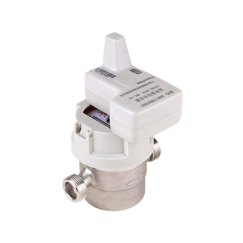
Designed for single-family homes and apartment risers. Available with a compact brass or stainless steel body, a local LCD display, and optional pulse output, M-Bus, RS485, LoRaWAN, or NB-IoT communication. The R-value can be selected as R160, R250, or R400 depending on the metering regulation in the destination country.
Used for prepaid water management and remote shut-off in rental properties, dormitories, and multi-tenant buildings. The valve can be closed by the platform when credit is exhausted or when a leak alarm is triggered. The valve remains fully open during normal metering so it does not distort the flow profile.
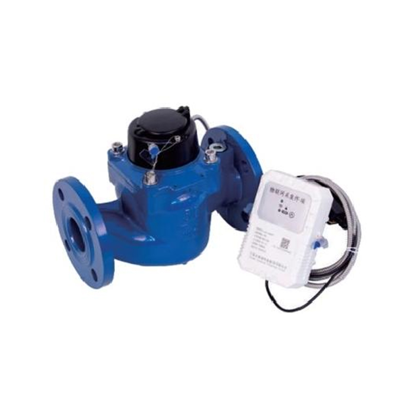
For commercial buildings, industrial plants, irrigation networks, and district metering areas. These meters use larger transducers and a stainless steel or ductile iron body. They support remote reading via NB-IoT or LoRaWAN, allowing the utility to monitor instantaneous flow and totalised volume without visiting the chamber.
The same ultrasonic measuring platform is used in heat metering applications. Pairing an ultrasonic flow sensor with a pair of temperature probes allows the meter to calculate thermal energy in district heating and central cooling systems. This is particularly relevant for projects that need both cold water and heat measurement from a single supplier.
 NB Bulk Ultrasonic Remote Water Meter for Commercial and Industrial UseThis ultrasonic meter with R400 range and IP68 protection suits cold and hot water networks, enabling reliable remote billing and leak detection for large-diameter installations.View Product →
 Ultrasonic Remote Heat Water Meter for Hot Water MonitoringEngineered for hot water up to 90°C, this meter supports AMR, remote billing, and leakage analysis, complementing projects that need integrated thermal energy measurement.View Product →
When a specification sheet states R160 or R400, it defines the ratio between the permanent flow rate Q3 and the minimum flow rate Q1. A meter with Q3 = 2.5 m³/h and R160 has a minimum flow rate of 2.5 / 160 = 15.6 L/h at DN15. The lower the minimum flow rate, the better the meter detects small night flows, dripping taps, and underground pipe seepage.
ISO 4064 sets the maximum permissible error in two zones. Between Q2 and Q4, the error must not exceed ±2% for cold water up to 30°C and ±3% for hot water above 30°C. Between Q1 and Q2, the error limit is ±5%. The transition point Q2 should be chosen as Q1 × 1.6 for meters intended for residential use; for high-accuracy industrial meters, some standards apply Q2 = Q1 × 2.5.
| Flow Point | Value | Meaning in Practice |
|---|---|---|
| Q4 (overload flow) | 3.125 m³/h | Flow that can be carried briefly without damage |
| Q3 (permanent flow) | 2.5 m³/h | The reference operating flow |
| Q2 (transitional flow) | 25 L/h | Boundary between error zones |
| Q1 (minimum flow) | 15.6 L/h | Lowest flow at which accuracy is guaranteed |
Selecting the correct R-value is not about choosing the highest number available. A meter with R400 has excellent low-flow sensitivity, but the stability of the flow profile at the 100 L/h rate is different from that at 15 L/h. For a utility that only needs to bill normal domestic consumption, R160 is usually sufficient. For water loss reduction programmes and secondary water supply systems, R250 or R400 gives a better chance of detecting small continuous leaks.
The factory calibration is performed under ideal straight-pipe conditions with no upstream disturbance. On-site, the installer must reproduce a sufficiently stable velocity profile if the meter is to achieve its declared accuracy class. The most common mistake is to install an ultrasonic water meter immediately after a partially closed valve or a sharp elbow without straightening distance.
For pit installation, the electronics and display must be protected against condensation and occasional flooding. An IP68-rated meter can remain submerged for short periods, but the communication cable entry point should still be sealed with a certified gland. When an NB-IoT module is used inside a metal pit, signal strength should be tested on site; an external antenna may be necessary. Further guidance is available in the article on ultrasonic water meter installation precautions.
An ultrasonic water meter has fewer mechanical failure modes than a vane-wheel meter, but it is still a precision electronic instrument. The most frequent issues in the field are fouled transducer faces, condensation inside the register, battery depletion, and damaged communication modules. Most of these problems can be detected remotely because the meter continuously reports diagnostic flags.
| Task | Interval | Typical Indication That Action Is Needed |
|---|---|---|
| Visual inspection of display and terminal seal | Every 6–12 months | Fogging, corrosion, missing lead seal |
| Communication test via AMR platform | Monthly | No data received for 30 days |
| Check for air lock at the meter | Each reading visit | Flow display fluctuating at zero consumption |
| Verify battery voltage and alarm status | Every 12 months | Low-battery alarm in reading system |
| Periodic verification against reference standard | Every 4–6 years | Customer complaint about high or low bill |
One point that surprises many operators is that an ultrasonic water meter can continue to register total volume even when the display panel is removed or the battery is disconnected. Data stored in non-volatile memory should be read out before any component replacement. When the meter is returned to the factory for recalibration, the factory test bench checks the meter at Q1, Q2, Q3 and Q4. If the measured errors are within the limits, the meter can be resealed and placed back in service. If not, the transducer assembly or electronic module is renewed.
Buying ultrasonic water meters directly from a factory is different from buying from a local distributor. The buyer has more influence over the product configuration, quality control, packaging, and documentation, but also carries the responsibility of defining the technical specification clearly. The following checklist is based on the purchasing processes that we see from overseas water companies, housing developers, and irrigation contractors.
| Criteria | What the manufacturer needs to confirm |
|---|---|
| Nominal diameter and connection | DN15 to DN40 threaded or DN50 to DN200 flanged; standard or custom thread length |
| Accuracy class and R-value | R160 / R250 / R400; whether MID pattern approval is needed for the destination country |
| Fluid temperature | Cold water only, or combined cold/hot water up to 90°C for heat applications |
| Communication protocol | NB-IoT, LoRaWAN, M-Bus, RS485 Modbus, pulse output, or short-range radio |
| Power supply | Internal battery designed for 8–10 years, or external 24V DC, or AC adapter |
| Protection rating | IP65 for indoor cabinets or IP68 for submerged meter pits |
| Compliance files | ISO 4064 test certificate, MID/CE certificate, battery certificate, material test reports |
| Spare parts and tooling | Spare cover, gaskets, mounting brackets, and a communication test tool |
Since 2002, our manufacturing base in Ningbo has supplied water meters to Asia, Africa, Europe and South America. The company profile on the official website describes the ISO 9001 quality system, ISO 14001 environmental management, and ISO 45001 occupational safety management that cover the production process. Buyers are also welcome to define custom communication protocols, housing colours, captured-screw dimensions, and documentation packages to fit local tender requirements.
The shift from reading meters once a month to collecting hourly or even six-second interval data fundamentally changes the way a water utility manages its network. Ultrasonic water meters are particularly well suited to this shift because they produce electronic data natively. The low-flow accuracy of the ultrasonic principle means a utility can identify a continuous leak of 20 L/h at a single household connection, which is too small to be seen on a mechanical meter.
For a project that combines flow measurement with pressure management, a remote electromagnetic water meter can complement ultrasonic meters. The  Remote Electromagnetic Stainless Smart Water Meter for Conductive LiquidsFeaturing a stainless body, IP68 rating, and bidirectional flow, this meter provides low-pressure-loss measurement with remote data access, ideal for water treatment and distribution.View Product → electromagnetic measuring principle is particularly useful in water treatment plants and distribution points where conductive liquids need to be metered with the lowest possible pressure loss. By selecting the correct measuring technology for each point in the network, a utility avoids the cost of overspecified meters without giving up data reliability.
For a DN15 meter with Q3 = 2.5 m³/h and R160, the minimum guaranteed flow is 15.6 L/h. Below Q1 the meter may still measure, but the error is outside the limits of ISO 4064. The practical minimum measurable flow depends on the internal pipe diameter and the resolution of the transit-time measurement. Our DN15 meters typically start to produce a stable flow reading at 3–5 L/h, which is useful as an indicator but not for billing.
Most battery-powered ultrasonic meters are fitted with a high-capacity lithium battery rated for 8 to 10 years. The actual life depends on the communication interval: a meter that transmits hourly NB-IoT data will consume more energy than one that uses an annual walk-by reading. If the battery is replaceable, the register is separated from the measuring tube and the replacement can be done without removing the meter from the pipeline.
Yes. The transducer arrangement and the measuring tube can be designed for water temperatures up to 90°C or 120°C. For heat metering, the same measuring principle is applied together with two temperature sensors. Hot water meters require a different electronic calibration curve because the speed of sound in water changes with temperature. The meter must be ordered with the correct temperature class, not adjusted on site.
Air bubbles in the acoustic path change the effective speed of sound and can cause the meter to over- or under-register depending on the bubble position. Modern meters filter signal quality and raise an alarm when the sound path is disturbed. This is why the installation instructions call for an air vent upstream of the meter in high-rise buildings and long horizontal pipes.
It depends on the meter design. Meters with a fully unobstructed bore are sensitive to swirling flow caused by double elbows that do not lie in the same plane. A built-in flow straightener or a longer inlet section helps stabilise the velocity profile. If the manufacturer specifies 10 DN upstream, that length should be treated as part of the total meter installation length.
The first purchase price is higher than a mechanical meter, but the total cost of ownership is often lower when the comparison includes testing, maintenance, manual reading, and the value of saved water. A utility can reduce its night flow and identify customer-side leaks within days of installing ultrasonic meters. The recovered water revenue frequently pays for the meter investment before the battery reaches the end of its designed life.
The ultrasonic water meters shipped from our factory are produced in a 30,000-square-metre facility with an annual capacity of five million water meters. The production process includes transducer matching, PCB assembly, flow bench calibration, and a two-hour burn-in test before packing. Every meter is calibrated against a gravimetric reference test bench, and the calibration records are stored to allow batch traceability.
Because the same factory also produces mechanical meter bodies, brass and stainless steel fittings, ceramic valves, and register assemblies, the ultrasonic product line benefits from in-house supply chain control. This vertical integration shortens lead times for spare parts and makes it feasible to customise the meter construction for a specific national metering regulation.
prevNo next article
nextWho Is Responsible for the Water Meter in Your House? A Manufacturer's Guide


Address: No.168,LinMu Rd.,Zone B, Jiangbei investment Park, Ningbo, Zhejiang,China
Tel: +86-0574-83090480/+86-18892665118
Fax: +86-0574-83021045
Email: [email protected]
Web: https://www.keyturemeter.com/
Quick Links
Product
Mobile terminal
 Wholesale Potable Water Flow Meter Manufacturers