English
 Español


Yes. Most ultrasonic water meters require straight pipe runs upstream and downstream to deliver the accuracy stated on their label. When we test a single-path ultrasonic meter in our production facility, the calibration bench includes long straight sections precisely for this reason. If the same meter is mounted too close to a pump or a partially closed valve, the reading can shift by several percent, even though the meter itself has not changed.
For a typical transit-time ultrasonic water meter, the accepted installation rule is at least 10 pipe diameters of straight pipe upstream of the meter and at least 5 pipe diameters downstream. The upstream distance is measured from the nearest flow-disturbing fitting, such as a 90-degree elbow, tee, pump, or valve, to the meter inlet. The downstream distance is measured from the meter outlet to the next fitting.
These requirements are expressed in terms of pipe diameter because the physical distance scales with the meter size. A DN20 meter therefore needs about 200 mm of straight pipe upstream and 100 mm downstream. A DN50 meter needs about 500 mm upstream and 250 mm downstream. A DN200 bulk meter needs about 2 m upstream and 1 m downstream.
An ultrasonic water meter measures flow by sending high-frequency sound pulses through the water. Two transducers are normally mounted on the same flow tube. One transducer sends a pulse downstream, and the other sends a pulse upstream. Because the water is moving, the downstream pulse travels slightly faster than the upstream pulse. The meter measures the time difference and converts it into an average flow velocity along the acoustic path.
This measurement method is fast, has no moving parts, and can detect very low flow rates, but it depends on a predictable velocity profile across the pipe. In a long straight pipe, the water flow becomes fully developed, meaning the velocity distribution is stable and symmetrical. The fastest water is in the center, and the slower water is near the pipe wall. A single-path ultrasonic meter uses one chord of that profile and assumes the rest of the profile follows the same pattern.
When pipe fittings disturb the water flow, the profile becomes twisted or asymmetric. Swirl can remain in the pipe for 20 or more pipe diameters. If the ultrasonic path happens to sample the faster side of the profile, the meter over-registers. If it samples the slower side, the meter under-registers.
This is not a mechanical fault. The meter electronics are still measuring the actual transit time difference across the path. The problem is that the path velocity no longer represents the average velocity across the whole cross-section. Straight pipe runs are therefore not an optional recommendation; they are part of the hydraulic design of the installation.
Different upstream fittings create different levels of flow disturbance. A single elbow creates a mild asymmetry. A partially open gate valve creates a high-velocity jet and severe turbulence. Two elbows in different planes create swirl that persists much longer. The table below gives practical starting values for a single-path ultrasonic water meter.
| Upstream condition | Upstream straight pipe | Downstream straight pipe |
|---|---|---|
| Single 90-degree elbow or tee | 10D | 5D |
| Two 90-degree elbows in the same plane | 15D | 5D |
| Two 90-degree elbows in different planes | 25D | 5D |
| Fully open gate valve | 10D | 5D |
| Partially open gate valve | 25D | 5D |
| Pump discharge with check valve | 25D | 5D |
| Concentric reducer or expansion | 15D | 5D |
These values assume a full-bore ultrasonic meter installed in a pipe of the same nominal diameter. If the pipe is old, scaled, or partially blocked, the straight pipe requirement can be longer. If the meter has multiple acoustic paths or an internal flow conditioner, the requirement may be shorter, but that should always be confirmed from the technical datasheet rather than assumed.
Insufficient straight pipe creates three distinct problems in an ultrasonic water meter installation: registration error, signal instability, and inconsistent low-flow performance.
The meter may read consistently high or low because it is measuring one disturbed part of the velocity profile. This is often only noticed when a comparison test is made against a calibrated test setup or another meter.
Swirl, air bubbles, and turbulence scatter the ultrasonic signal. The meter may show fluctuating instantaneous flow readings even when the actual demand is constant.
At low flow rates the velocity profile is already less stable. Short straight pipe magnifies this effect, making it difficult to detect small leaks and night-time flows.
A field case from our support history shows how important this is. A distributor in Europe installed a DN80 ultrasonic water meter only 3D downstream of a butterfly valve. Over the first month, the utility saw that night flows were suspiciously high. A portable test showed the meter was registering about 6% higher than the actual volume. The meter was moved to a location with 12D upstream straight pipe, and the offset dropped to below 1%. No component inside the meter had changed; the only difference was the hydraulic profile.
When you are planning an ultrasonic water meter installation, it helps to walk through the pipe route and identify every possible source of disturbance before choosing the meter position.
The best approach is to place the meter before, not after, the most disturbing fitting. For example, if a system has a filter and a pump, install the ultrasonic water meter on the inlet side of the filter with straight pipe in front of it, rather than directly after the pump discharge.
There are ultrasonic water meter designs that tolerate disturbed flow better than others. The main reason is the number and arrangement of acoustic paths.
A multi-path ultrasonic meter sends sound pulses along several chords at different heights within the pipe. The meter electronics combine those velocity measurements into a more accurate cross-sectional average. This reduces the error caused by an asymmetric profile, but it does not completely eliminate the need for straight pipe. A multi-path meter may work with 5D upstream and 2D downstream where a single-path meter would need 10D and 5D.
Some flow tubes have machined internal geometry that straightens the flow before the acoustic path. These meters can be installed with significantly shorter external straight pipe. However, the internal conditioner can also increase pressure loss and may be affected by water quality if debris accumulates.
Clamp-on ultrasonic flow meters measure through the pipe wall and are often used for temporary verification. They do not have the advantage of a machined flow tube. They are sensitive to pipe wall condition, transducer alignment, and the velocity profile. A clamp-on meter needs the same attention to straight pipe as an inline meter, sometimes more.
If the pipe layout is extremely compact and no ultrasonic meter can meet the straight run requirements, an electromagnetic water meter is a practical alternative. Because electromagnetic meters measure flow based on the voltage generated by conductive water moving through a magnetic field, they are less dependent on a perfectly symmetrical velocity profile. For this reason, we often recommend electromagnetic meters for retrofits in tight mechanical rooms and pump stations.
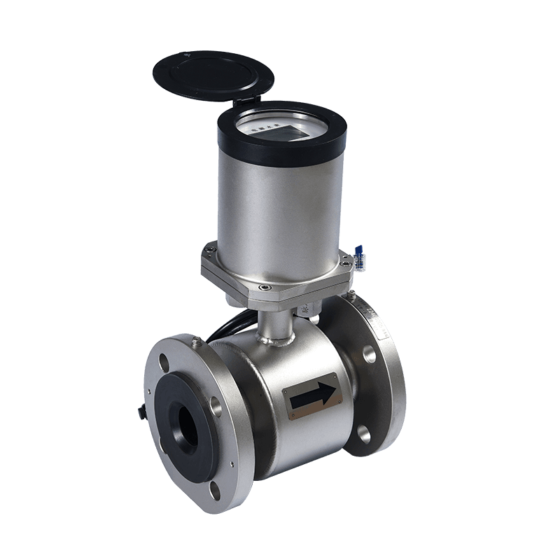 KM08-01 远程电磁不锈钢智能水表适合在直管段不足的紧凑机房和泵站中替代超声波水表,可在有限空间内完成改造并配合远程监控。View Product →
Straight pipe is the most important installation condition, but it is not the only one. We recommend the following installation sequence for every ultrasonic water meter we manufacture.
Vertical pipe installation is acceptable if the flow direction is upward. An upward flow keeps the pipe full and allows gases to travel upward instead of lodging inside the meter. Downward vertical flow is risky because the pipe may not stay full at low flow rates.
Large-diameter ultrasonic water meters from DN50 to DN200 are used in distribution mains, irrigation networks, and industrial sub-metering. These locations often contain pumps, control valves, strainers, and complex manifold layouts. A single-path ultrasonic meter can be difficult to install in these conditions because a 10D requirement on a DN150 line means 1.5 m of clear pipe before the meter.
In practice, we design large-diameter ultrasonic meters with a multi-path transducer arrangement and a machined bore. This helps average out residual flow asymmetry and reduces the required straight pipe compared with a simple one-path design. Even so, our technical drawing for each model states the minimum upstream and downstream distances. We never recommend removing all straight pipe unless the meter is explicitly marked with a low straight-run approval or has an integrated flow conditioner.
For water utilities and plant engineers, the larger the meter, the more important it is to obtain the installation drawing before civil works are completed. It is very expensive to cut and reposition a DN200 meter after the concrete chambers and pipe supports have been built. A quick review of the pipe layout during the design phase can prevent a chronic accuracy problem that remains hidden for years.
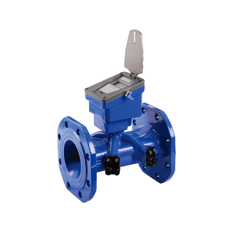 KM07-03 大口径超声波远程水表适用于DN50至DN200等大规格工业计量,安装前需仔细核对图纸,以确保直管段满足精度要求。View Product →
A simple visual inspection is often enough to reject a poor installation. Walk to the upstream side of the meter and identify the nearest fitting. Measure the distance from that fitting to the meter inlet face. Divide the distance by the nominal pipe diameter. If the result is lower than the required number of pipe diameters, the straight run is not sufficient.
You can also perform a practical field verification with a bucket or a calibrated tank. Run water at a stable medium flow for a measured amount of time and compare the collected volume with the meter total. Repeat the test at a low flow and at a high flow. If the error changes with flow rate, the cause is often a disturbed velocity profile rather than a meter calibration problem.
For a more precise check, compare the ultrasonic meter reading with another flow meter installed at a location that satisfies the straight pipe requirement. This is common when a portable clamp-on ultrasonic meter is used as a reference. It still needs its own straight pipe, so the best reference point is often a pipe section well downstream or upstream of the main meter where elbows and valves are absent.
Our engineering team also reviews installation drawings before shipment. If you are uncertain about a compact pipe layout, send us a simple sketch with pipe diameters, fitting positions, and flow direction. We will tell you whether the proposed location is acceptable and, if not, suggest an alternative meter type. You can also review our practical installation notes for more detail: ultrasonic water meter installation precautions.
In most cases, no. A single 90-degree elbow creates a strongly asymmetric velocity profile that can last for many pipe diameters. The recommended minimum is usually 10D upstream, and a higher value is safer if the elbow is close to a pump or valve. Installing immediately after the elbow may still produce usable readings, but the error can exceed the meter specification.
Yes, although the downstream distance is shorter than the upstream distance. The downstream pipe provides a controlled pressure and velocity condition at the meter outlet. It also prevents a downstream fitting from creating a low-pressure zone that could disturb the flow inside the meter body. The standard minimum is usually 5D.
Yes. The straight pipe requirement is expressed in pipe diameters, which means the actual physical distance grows with the meter size. A DN20 meter with a 10D requirement needs 200 mm of straight pipe, while a DN200 meter needs 2 m. This is why large-diameter installations need more planning space.
A flow straightener can reduce swirl, but it is not a perfect replacement. It must be installed with a recommended distance upstream of the meter and a clean pipe section downstream. Flow straighteners also collect debris and scaling over time, which changes their performance. We prefer a true straight pipe run whenever the layout allows it.
No. Single-path meters are more sensitive to flow profile disturbance. Multi-path meters are generally more stable. Some compact residential meters are designed with internal flow conditioning to reduce external pipe requirements. Always check the installation section of the meter datasheet instead of applying a generic rule.
First, check whether the meter model has a shorter straight pipe requirement due to multi-path measurement or internal conditioning. If the space is still too tight, consider an electromagnetic water meter or adjust the pipe layout to move the meter to a better location. Permanently accepting an undersized straight run will make the meter data unreliable.
At zero flow, there is no velocity to measure, so the straight pipe requirement mainly affects low flow detection and metering accuracy above the starting flow rate. In a disturbed flow profile, low flow readings are often unstable, which can hide leaks and make night-flow analysis difficult.


Address: No.168,LinMu Rd.,Zone B, Jiangbei investment Park, Ningbo, Zhejiang,China
Tel: +86-0574-83090480/+86-18892665118
Fax: +86-0574-83021045
Email: [email protected]
Web: https://www.keyturemeter.com/
Quick Links
Product
Mobile terminal
 Wholesale Potable Water Flow Meter Manufacturers